Thermoforming Design for Manufacturing (TFM DFM)
Thermoforming is an affordable technology for creating packaging, trays, panels, housings and more. These parts are durable, inexpensive and relatively quick to produce. Thermoformed parts can be rigid or flexible; opaque or translucent; and come in a variety of materials with different mechanical, thermal and chemical properties.
Although thermoforming has some design limitations and cannot achieve the fine detail of injection molding, machining or 3D printing, thermoforming offers lower startup costs than injection molding or machining and a lower cost per part than 3D printing, making it a good solution for small- to medium-sized orders.
Because of these design restrictions, it is essential to follow certain guidelines when creating thermoformed parts. Doing so will help create more accurate and durable parts in addition to prolonging the life of the molds for each part. We put together this guide to cover the general principles of thermoforming design for manufacturing as a place to start thinking about any thermoforming project.
How Thermoforming Works

Fundamentally, thermoforming works by drawing a hot sheet of thermoplastic down onto a mold. Each draw uses a single sheet. These sheets can be formed into one or multiple parts depending upon the size of the part. Increasing the number of parts created per draw is one of the best ways to decrease the cost per part of thermoformed products.
After the hot thermoplastic has been drawn down over the mold, a vacuum may be used to suck out any air and accurately reproduce the details of the mold. This process is referred to as vacuum forming. Once the part has cooled, any excess plastic from the sheet is trimmed away leaving a finished part. These cuts can occur at the base of the part, along the wall or in any number of custom variations to create features like holes and slots.
Before thermoforming can begin, manufacturers need molds to produce their final products. These molds can be 3D printed, cast, or machined. If the final product is going to be translucent or transparent, the mold may need custom finishing like sanding or polishing in order to achieve optimal surface finish as the finish will pick up on the parts. Depending upon the technology and material used, the lifetimes of these molds can range from hundreds of forms to permanent tooling for unlimited forms.
How to Design Parts for Thermoforming
Because thermoformed parts are formed from a single sheet and need to be pulled off of a mold once formed, there are some specific design factors that must be considered when developing thermoformed parts. These include draw ratio, material thickness, draft angles and detail. When designing for thermoforming, it is also important to allow for shrinkage as the hot plastic cools. This will not only ensure that the finished parts have the desired dimensions, it will also allow the part to be lifted off of the mold without damaging the part or the tool.
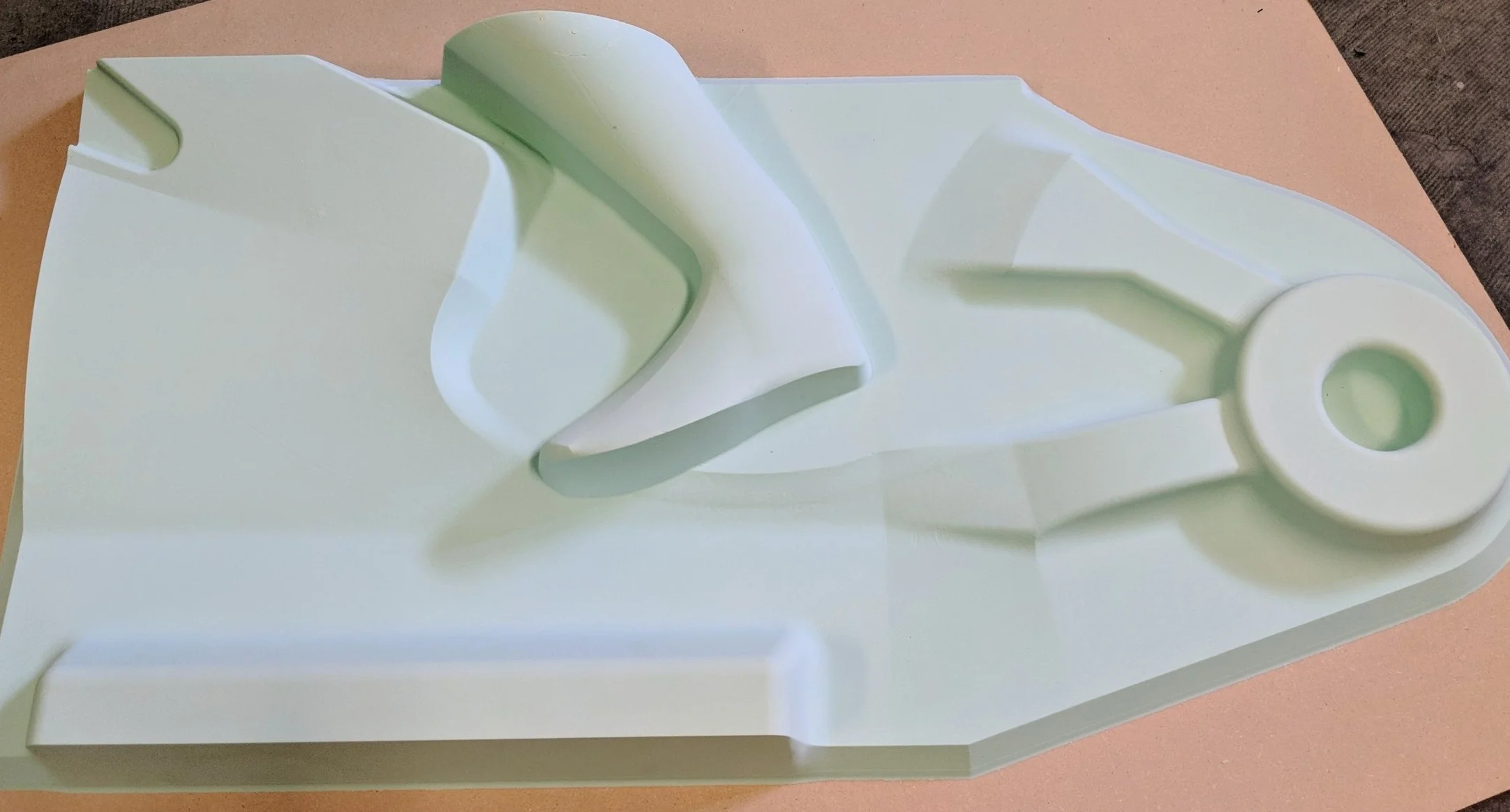
Thermoform buck for motorcycle model made from high temperature urethane foam, 40# density
Draft Angles
Because plastic sheets shrink when they cool, all thermoformed parts require some draft to ensure they can be removed from the mold. If the mold is of an internal cavity only, also known as a female mold, 2-5 degrees of draft is usually sufficient. If your mold includes raised features, it must have a minimum draft of 4-8 degrees to compensate for shrinkage during cooling. Small undercuts are possible with thinner plastics, however, larger undercuts or thicker materials will need to be made in multiple parts, leading to increased production time and expense.
Draw Ratio
When designing a part to be thermoformed, draw ratio, or the proportion of depth to the width of the part, is one of the most important considerations. The depth of any cavity cannot exceed a 4:3 ratio of depth to width. For optimal results, we recommend keeping as close to a 1:1 ratio as possible.
To find the overall draw ratio, divide the total surface area of the 3D part by the part’s 2D footprint as seen from the top. Though there are other details that determine design compatibility, draw ratio is a good place to start.
Size
Our thermoformers have bed sizes starting at 19” x 17” and a max draw depth beginning at 11.5 inches. Within these ranges we can also adjust forming windows to accommodate smaller sizes of 5” x 5”, 11” x 11” and 15” x 15” to reduce material costs for smaller parts. For larger parts, we can form up to 4’ x 8’, but this requires a custom vacuum box and sheet cut.
To determine the length and width of your window, we recommend adding your part’s height to both its length and width. For example, a part that measures 8” x 4” x 2” would need at least a 10” x 6” window.
Details and Mold Making
The highest amount of detail and dimensional accuracy will be on the mold side of the part and can achieve an accuracy similar to the accuracy of the tooling process. If dimensional accuracy on the other side of the sheet is important, expansion and contraction need to be taken into account for your chosen material and designed into the mold.
Thickness
Thermoplastic sheets come in a wide variety of thicknesses, ranging from 0.020” to 0.250”. When thinking about how thick of a sheet to use for your part, it’s often helpful to find the thinnest point of your part for each sheet. To do this, divide the sheet’s thickness by the draw ratio of the mold. This will give you an idea of the thinnest point for your part, though, in reality, it will vary above and below this.
The thinnest point will usually be at the corners of internal cavities, followed by the corners of ridges. To minimize thinning, we recommend keeping radii on corners and edges as large as possible, especially at the bottom of cavities and channels. As a general rule of thumb, parts should have a minimum fillet radius of ½ the material’s original thickness on the inside of the bend.
Male (Positive) vs Female (Negative) Molds
Male molds control the inside surface of a part while female molds control the outside surface of a part. The opposite surface is uncontrolled and can vary due to plastic thickness and thinning. Male molds tend to thin less than female mold but require more draft. Recommended draft for male molds is 4 degrees while for female molds it is only 2 degrees.
Common Issues that Can Occur when Thermoforming
Excessive thinning from high draw ratios and sharp corners. Try reducing draw or adding fillets to your design.
Webbing or bunching of material during draw. Spread features out more to allow plastic to stretch into recesses.
Plastic Shrinkage. Every plastic has a unique shrink rate. Calculate that shrink and adjust the mold size to accomodate.
Collapsible Tooling and Undercuts. These can be very tricky and require a great deal of experience. Please consult an expert.
Thermoforming Tolerance Guidelines |
||
|---|---|---|
| ACTIVITY | TOLERANCE | GUIDELINE |
| FORMED MEASUREMENTS | +/-0.020” | Additional 0.001” per Inch beyond 12” |
| DRILLED HOLE DIAMETERS | +/-0.005” | Holes Equal or Lesser than 1” |
| DRILLED HOLE DIAMETERS | +/-0.010” | Holes from 1” to 5” |
| SLOTS | +/-0.010” | Slot Equal to or Lesser than 1” Any Direction |
| SLOTS | +/-0.020” | Slots Greater than 1” |
| 5 AXIS TRIM | +/-0.015” | Trim Features under 5” |
| 5 AXIS TRIM | +/-0.020” | Trim Features Greater than 5” |
Thermoforming Materials
Thermoforming materials like HIPS, PETG and ABS offer a range of mechanical, chemical and aesthetic properties. Thermoformed parts can rigid or flexible; transparent or opaque; and food-safe, heat-resistant, chemical-resistant, or UV-resistant. Below are our most commonly used materials for thermoforming. To get more information about any material, check out the included data sheet for all the specifications.
HIPS (Polystyrene)
Our most commonly-used material. Inexpensive, functional material that can be brittle at low temperatures and can off-gas at higher temperatures. Used for packaging trays, covers and light-duty structural pieces. Food-safe versions available.
PETG (Polyethylene Terephthalate) (Polyester)
Moderately inexpensive material with good water and oxygen barriers. Able to stand up to substantially lower temperatures than HIPS. Often used for food-safe applications, freezer packaging and water bottles.
ABS (Acrylonitrile Butadiene Styrene)
Medium-cost impact-resistant engineering plastic which can be flame retardant or UV resistant when blended with other materials. Used for high-end packaging and moderate-load structural components.
Kydex T (ABS/PVC) or Kydex 100 (Acrylic/PVC)
Expensive flame-retardant engineering plastic with high impact resistance. Used for moderate-load structures, covers and enclosures that require fire resistance. Kydex 100 is our go-to material for radomes.
PC (Polycarbonate)
Medium- to high-cost engineering plastic with high stiffness, impact strength and temperature resistance, plus options for UV and scratch resistance. Often used for glass replacements on phones, TVs, lights or glasses, as well as high-temp applications. Harder to form than most thermoplastics, especially for fine details.
PE, HDPE or LDPE (Polyethylene)
Moderately hard, inexpensive plastic with high chemical resistance. Does not off-gas at high temperatures. Chemical and thermal durability makes it well-suited for chemical-resistant containers. Higher shrink rate than other materials, which lowers tool life and increases variability between parts.
PP (Polypropylene)
Moderately-priced alternative to PE which improves thermal and mechanical properties. Higher level of chemical resistance than most plastics. Can be used as an engineering plastic. Used for chemical-resistant applications, including food contact.
PVC (Polyvinyl Chloride)
Hard engineering plastic with strong mechanical properties as well as high chemical and electrical resistance. Can be made rigid or flexible. Used for certain chemical-resistant containers.
Acrylic
An inexpensive, rigid and brittle plastic with relatively high UV resistance. More difficult to form than other plastics. Not intended for tight bends or details. UV resistance makes it well-suited to outdoor applications.
Molds for Thermoforming
Traditionally, molds for thermoforming have been machined from urethane or aluminum. Now, 3D printing has become an excellent choice to produce tooling for parts smaller than 11” x 15”. 3D printed molds, especially those produced with Multi Jet Fusion printing, significantly lower the cost per part and speed up production time when compared to machined molds. Moreover, they can easily achieve complex shapes like undercuts that would be expensive or impossible to machine.
Ultimately, each technology offers different strengths for the tooling process. Molded tooling, for example, is good for creating multiple long-lasting molds. Machined tooling is a better option for making large molds, and, depending on the material used, can be permanent or semi-permanent. Even among 3D printed molds, there are different ideal applications for each type of 3D printer.
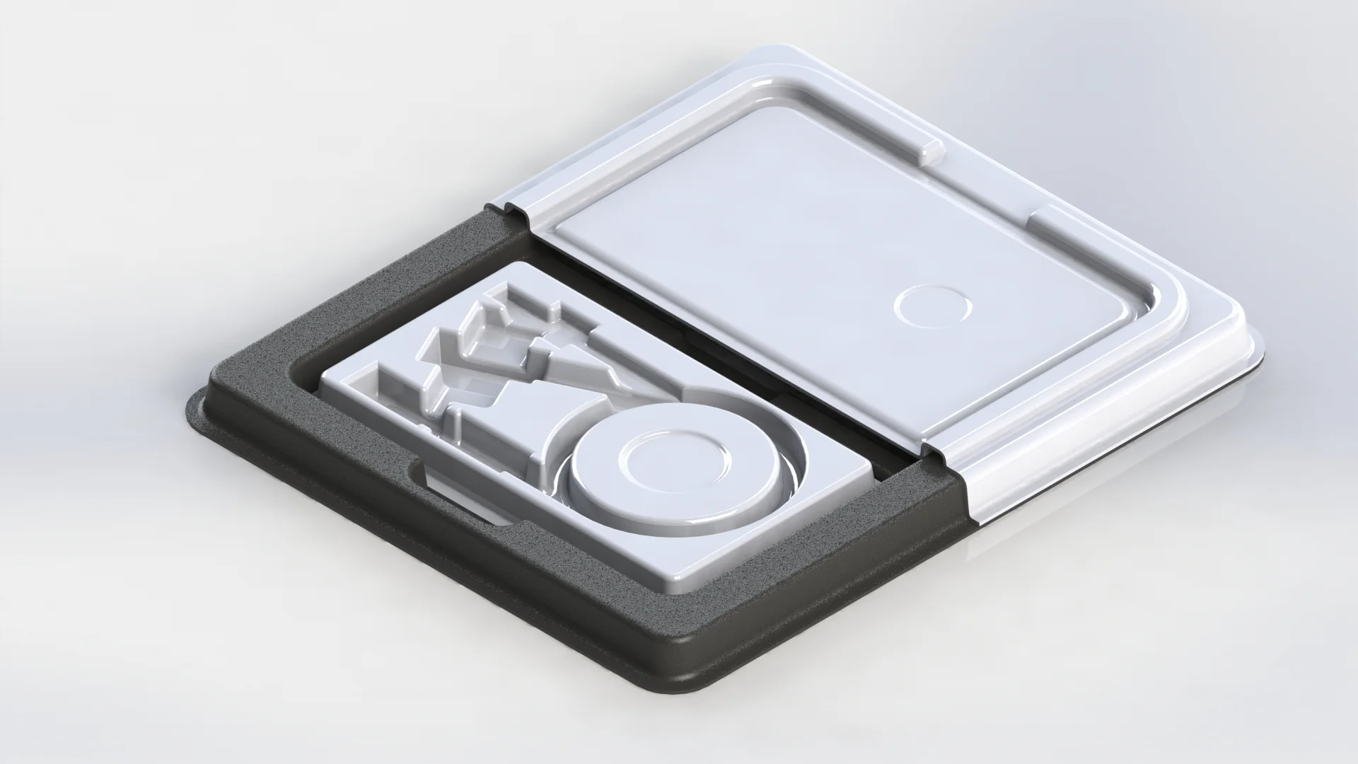
CAD 3D rendering of custom thermoform packaging and inserts
Types of Molds
Multi Jet Fusion (MJF)
The overall best tooling option for parts smaller than 15”x11”
The cheapest print option
High accuracy
Permeant tooling
Generally does not require additional finishing for opaque plastics
Aluminum-Filled Urethane
Create long-lasting tooling or multiples of a tool at a lower price than printing
Requires a 3D printed or machined master mold
Permanent tooling
Cheaper to reproduce in multiples than 3D printing, easily get high level of finish for polished parts
Machined Wood/MDF
Absolute cheapest option for medium to large tools for prototyping
Life is less than 50 forms
Poor to average accuracy
Machined Urethane Foam
The best option for larger, permanent tools where matte surface finish on tool face is acceptable
Average to good accuracy
Machined Aluminum
Permeant tooling
Used for automated, high-volume production with fast heating and cooling cycles
Good to excellent accuracy
Best surface finish of any mold, needed for high polish on mold side or clear parts

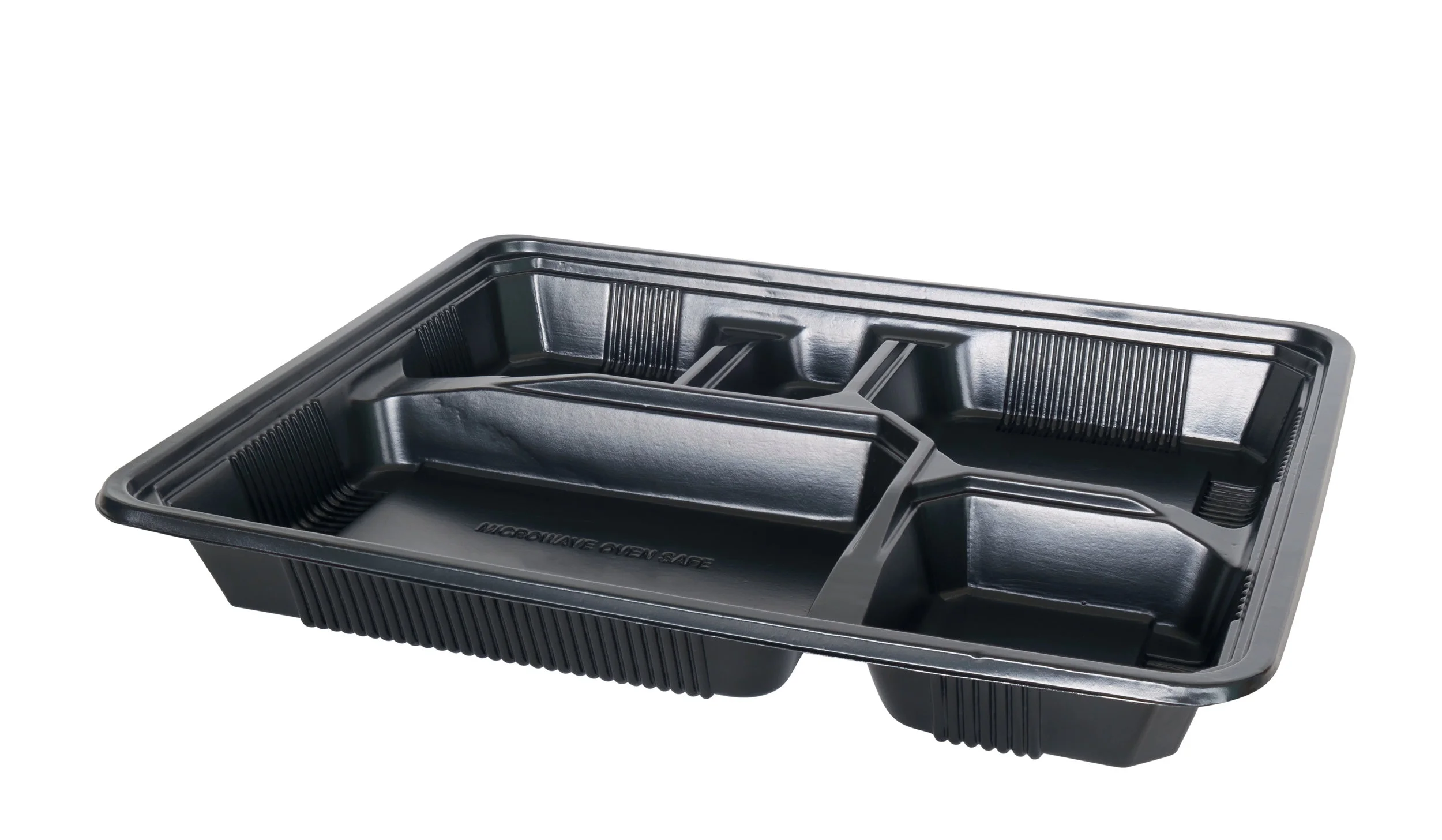
Cast Aluminum Composite Tooling and formed material handling tray from black High Impact Polystyrene (HIPS)
Trimming
Once the thermoplastic sheet is formed around the mold, it must be trimmed of excess material to create the final part. The type of cut used at this stage will impact the cost and speed of the finishing process. Trimming in generally done on a 3 Axis or 5 Axis CNC mill or if simple enough can be done with a hand router or on a table saw. Most capable forming shops will employ many different CNC machines and other tools to give great versatility in the trims they can accomplish.
In addition to creating the final part shape via trimming the outline from the formed mold trimming is vital to creating other features in a model like mounting holes, openings, vents and much more.

Vertical Cut
Most common cut
Creates a lip around the part a specified distance from the wall
Recommended minimum lip of 1/16”
Can be done on 3 Axis CNC or hand trim with end mill or router bit
Horizontal Cut
Second most common cut
Cuts the wall at a specified height
Primarily used for aesthetics or for fitting parts together
Can be done on 3 Axis CNC or hand trim with saw bit
Hole Cutout
Holes of most shapes can be cut out of a flat surface
Generally requires a small radius when used in corners (1/8” recommended, 1/16” achievable)
Can be done on 3 or 5 Axis CNC
Custom Cut
Varies from a multi-height horizontal cut to a complex, organic cut across multiple surfaces
Requires 5 Axis CNC milling
Finishing
Custom finishes are a great way to add improved aesthetics and functionality to thermoformed products. Like all of our products, we offer a range of finishes for our thermoforming services.
Custom Painting
Custom paint can be applied to formed parts to achieve a variety of colors and lusters. Custom pantone and RAL color matches available as well as lusters from flat to high gloss.
ESD Coating
A clear ESD coating to give your plastics electrical discharge that can be applied to plastics including PETG, ABS and PVC
UV Clear Coat
A clear coat (matte or gloss) that extends the life of plastics in outdoor applications
Sandblast
Adds light diffusion to clear part or high-quality matte texture to opaque parts
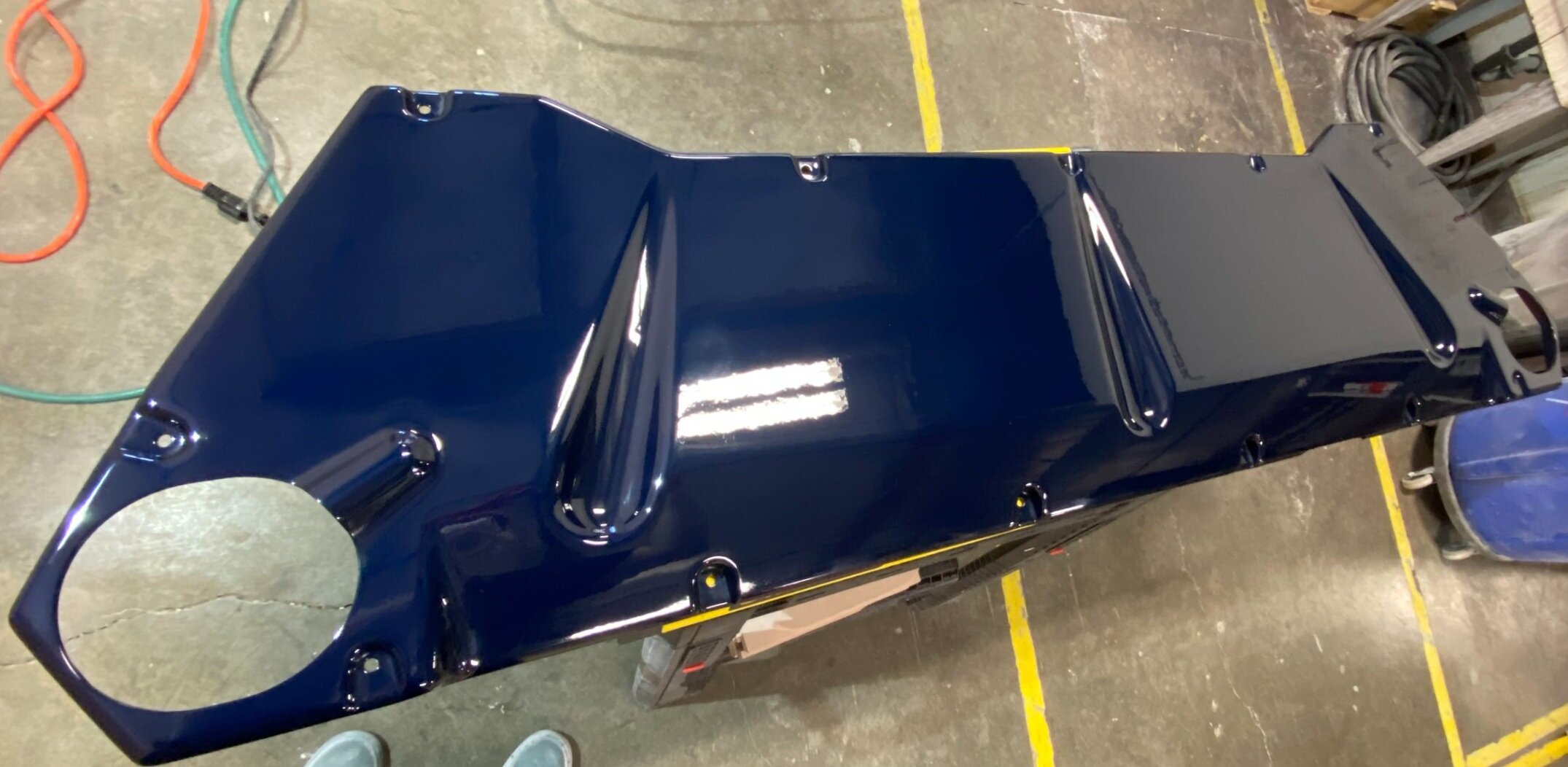
High Gloss Clear Coat on Automotive Panel
Get a Quote on Your Thermoforming Project Today
Thermoforming is a great plastic manufacturing technology with a wide range of applications. When paired with 3D printed tooling, it gains even more utility.
If you want to get started with a thermoforming project, RapidMade can help. Get started today by getting a free quote and design analysis in under 24 hours using our quote tool, or learn more by contacting us or one of our regional sales representatives.